 Addify
Stand Blueprints - Technical Drawings From Any Mesh
 by Loops3D
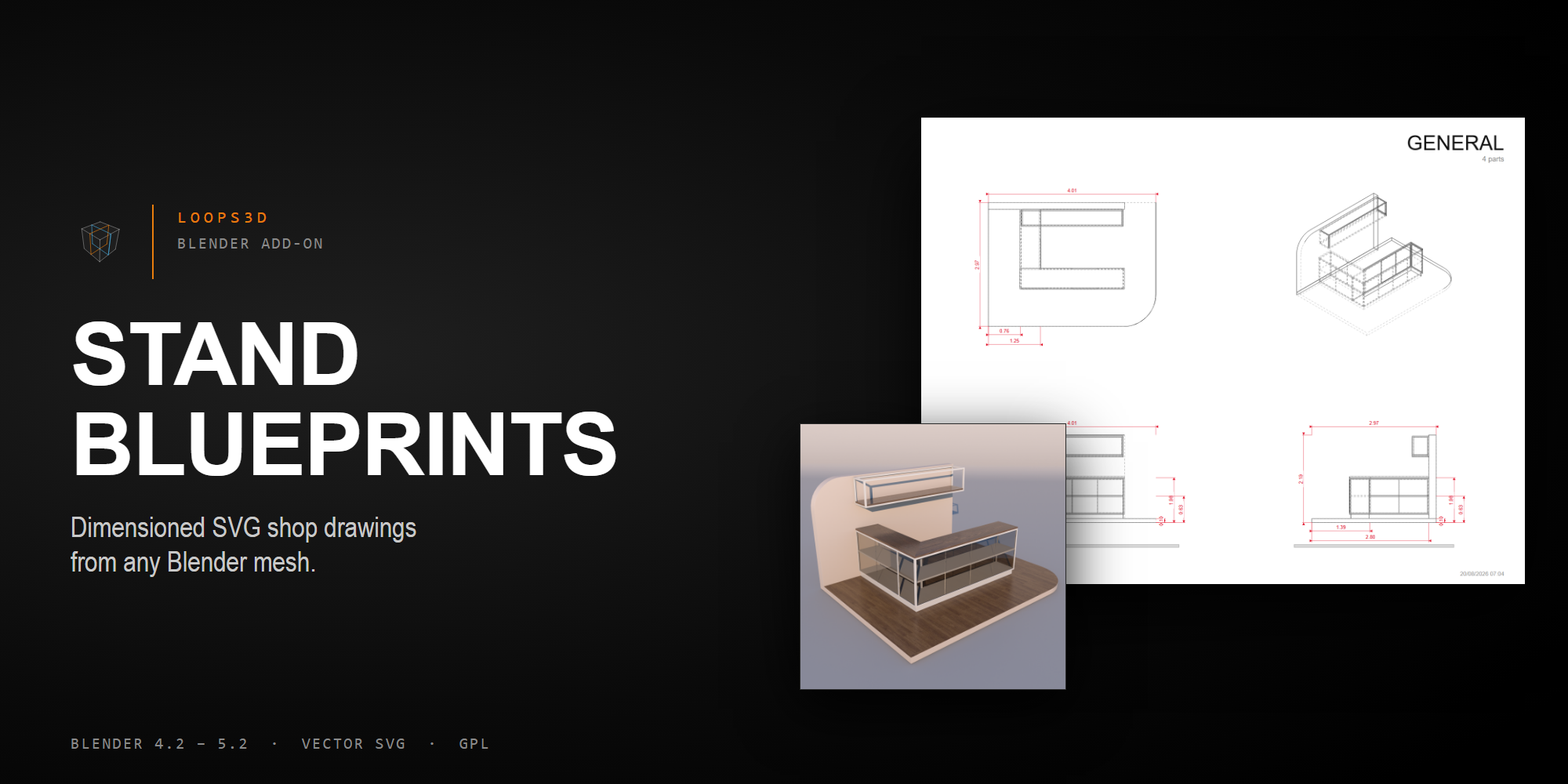

You modelled it. Now the shop wants a drawing.
You finish the stand, the booth, the counter, the set piece — and then somebody asks for measurements. So you open a new file, orbit around, type dimension after dimension by hand, and half a day is gone. Do it again after the client changes one panel.
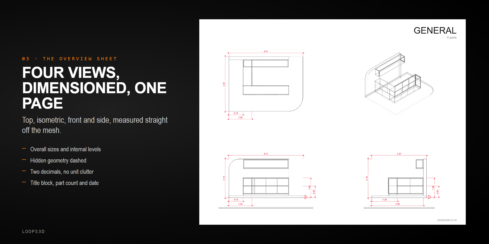
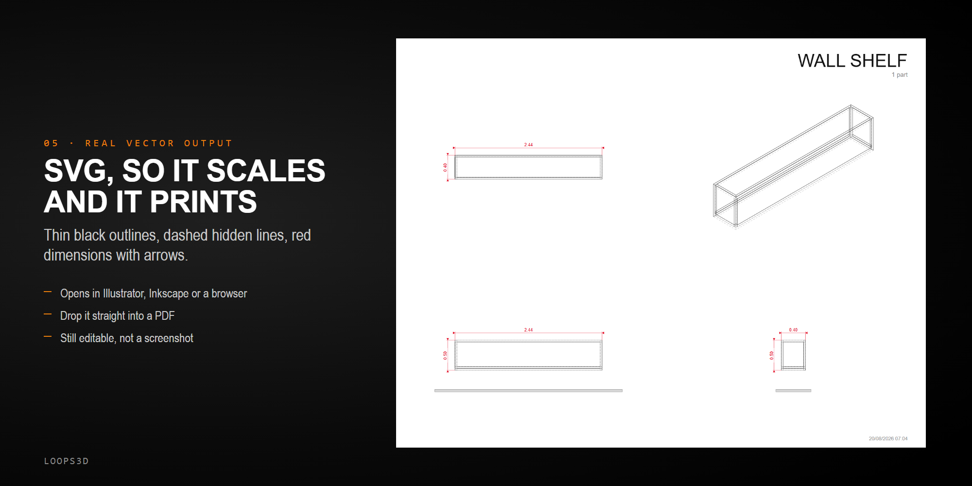
Stand Blueprints does that step for you. Select your parts, press one button, and you get a finished technical sheet: top view, isometric, front and side, with the dimensions measured straight off the mesh — in vector SVG, ready to print or hand to the shop.
It was not written as a demo. It was written for real exhibition-stand jobs, and the sheets in these screenshots are the same sheets that go to the fabricator.
How it works — three steps
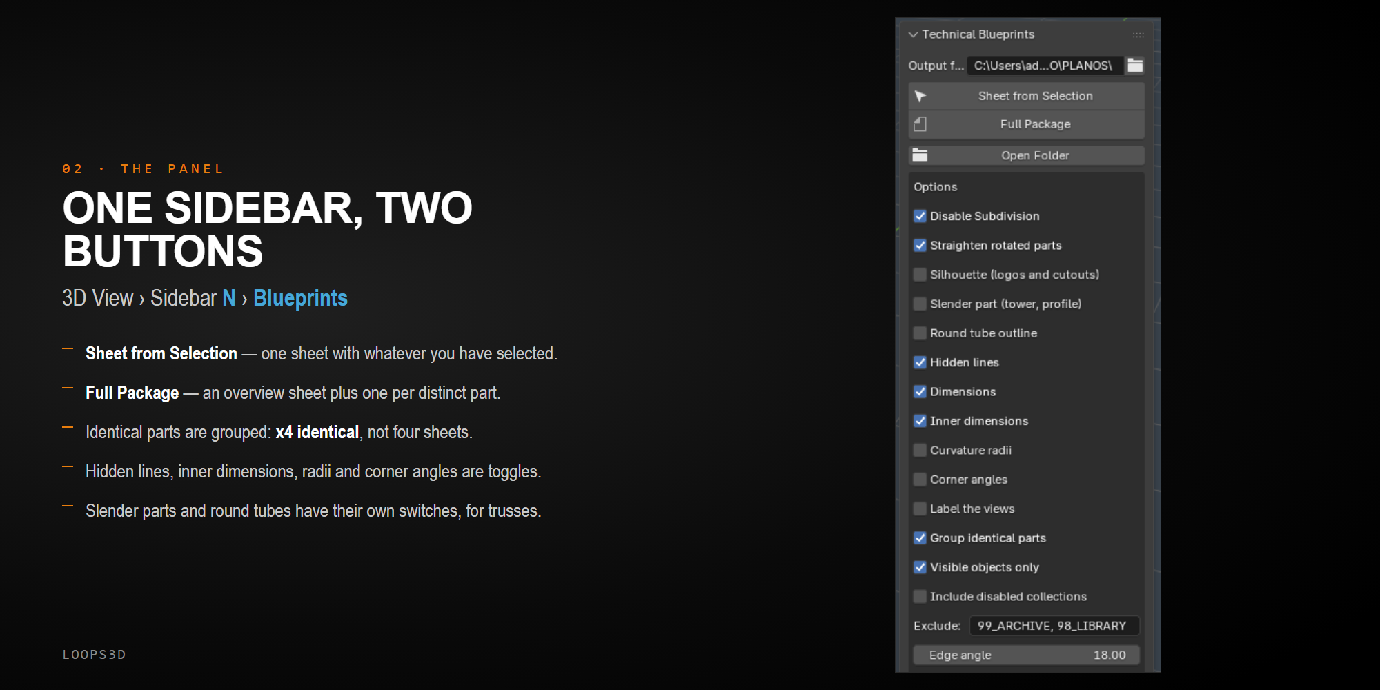
1. Point it at a folder. One field at the top of the panel. That is the whole setup.
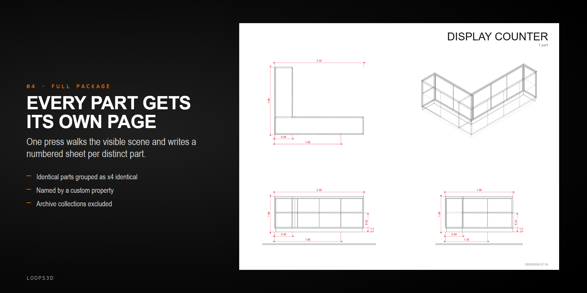
2. Press a button. Sheet from Selection gives you one sheet with whatever you have selected. Full Package walks your visible scene, groups the parts that are identical, and writes an overview sheet plus one numbered sheet per distinct part.
3. Open the SVG. Clean vector: thin black outlines, dashed hidden lines, red dimensions with arrows, title block top right. Print it, drop it in a PDF, or keep editing it in Illustrator or Inkscape — it is real vector geometry, not a screenshot.
What it measures for you
Overall size of every view, in meters, two decimals. Internal levels — shelf heights, base heights, the steps a fabricator actually needs. Hidden lines dashed, so you can read what is behind the front face. Curvature radii on real arcs. Corner angles. Every one of these is a checkbox, and the defaults are the ones that survived real jobs.
The switches that exist because a real job needed them
Silhouette (logos and cutouts) — traces a logo panel through its UVs, so the letters come out legible and the dimensions measure the artwork, not the plate that carries it.
Slender part (tower, profile) — lays a long piece down and spreads it in bands across the page. A truss tower went from 148 px/m to 492 px/m: three times the scale, same sheet.
Round tube outline — a truss is many-sided cylinders with no sharp edges, so an edge-angle pass draws a row of dots. This outlines curved parts per view instead.
Straighten rotated parts — a piece rotated inside its own plane inflates its bounding box and lies about its size. This draws it on its own plane, so the numbers are true.
Group identical parts — four identical shelves become one sheet marked x4 identical, not four sheets.
Exclude collections and Disable Subdivision keep your archive out of the package and your mesh editable.
Naming the parts
Add a custom object property called blueprint_name and that becomes the title of its sheet, so polySurface306 prints as BAR COUNTER. Without it, the object name is used, cleaned up.
Who this is for
Exhibition and booth designers, furniture and millwork, set and prop builders, product and retail display designers — anyone who models in Blender and then has to hand somebody a drawing with numbers on it.
What you get
A single-file add-on, installed the way you install any Blender add-on. Works in Blender 4.2 through 5.2. No dependencies beyond what ships with Blender. Panel lives in 3D View, Sidebar (N), Blueprints tab.